Latest update 2016-08-21
Updated links 2021-07-31
How to setup a NAZE32 and NazeMini
For Airplane and Flying Wings for Return to Launch functions.
Change the direction in the servo TAB.
Endpoints should be set in the Gui and not in the Transmitter.
fw_gps_maxcorr = 20 // Max Roll input from GPS (For Flying wings set to >=30)
fw_gps_maxclimb = 15 // Max Climb input
fw_gps_maxdive = 15 // Max Dive input
fw_gps_rudder = 15 // Max Rudder input if rudder is available
GPS modes Need to be activated together with Angle or Horizon modes.

Passthru = Manual flight Mode
Acro = Normal mode
Baseflight Gui now have a working servo mixing tab to use.
Before it was supported by Gui i created a simple
Windows App to setup Custom Airplane
Download ServoMixer_CLI.exe (right click save as!)
 Smix = Mixer ID
Servo = OutputServo
Input = Selected source
Rate = % rate and reverse with minus.
Speed = Higher is faster.(3 gives a nice speed for Flaps )
Min/Max = Endpoints 0 - 100 // 50 = Centerpoint
AUX select = Activate the rule with a AUX switch. zero for always active.
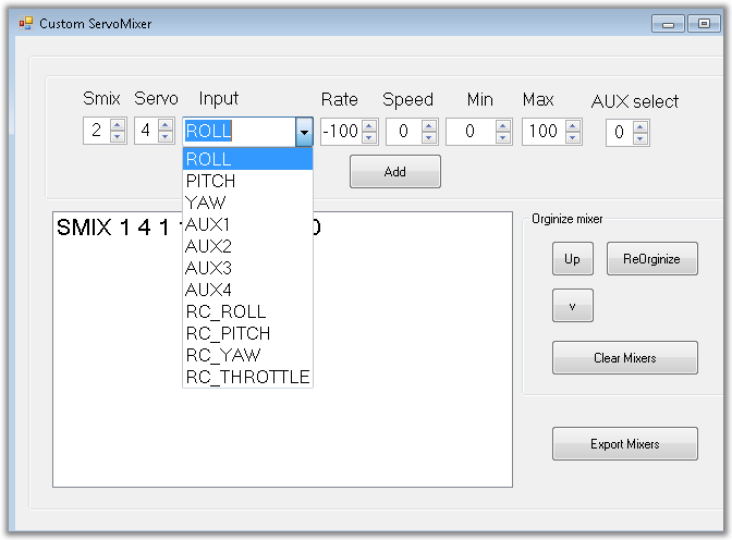
Create new rules
Select Output servo,Input,Rate, Min, Max and controllBox
Press Add to complete.
Add the mixers you need for your model.
 Mark a rule to edit it.
Press modify to save the modification.
Organize the list and move rules up or down.
Clear the list or fix the number order with
Reorganize button
Export mixers when done.
 Edit the mixers manually before exporting.
You can Copy the text and paste it in Baseflight CLI intercace.
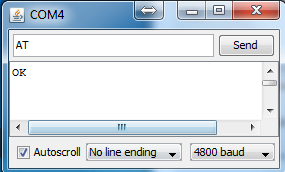
Or select correct Comport and Send it direct to the NAZE board.
Baudrate is set to 115200.
Make sure The Comport is closed and no other programs is
connected.

A CLI window will be shown to verify the communication.
Press Back to close the comport again.
Now you can connect Your Baseflight configurator to NAZE again.
Updated links 2021-07-31
How to setup a NAZE32 and NazeMini
For Airplane and Flying Wings for Return to Launch functions.
NOTE!
Magnetometer and Barometer is NOT needed for Airplanes.
A Naze32 Acro or AfroNaze together with a Gps module is sufficient.
Connection diagram for NazeMini

Owners manual from Abusemark
Connection diagram for Naze32

Owners manual from Abusemark
Most settings is available in the configurator.
The Settings for Elevator compensation is not active though it always show zero.
That is still a CLI command if you need to adjust it..
I recommend to install the latest dev for Fixed Wing.
It have all new fixes and functions.
Install it with the Firmware flasher in Baseflight Gui
New Updated Version
Here's video from Matthew Ogborne where he's testing FW_160622.
The more advanced F3 boards is not supported by Baseflight.
Magnetometer and Barometer is NOT needed for Airplanes.
A Naze32 Acro or AfroNaze together with a Gps module is sufficient.
Connection diagram for NazeMini
Owners manual from Abusemark
Connection diagram for Naze32
Owners manual from Abusemark
Most settings is available in the configurator.
The Settings for Elevator compensation is not active though it always show zero.
That is still a CLI command if you need to adjust it..
I recommend to install the latest dev for Fixed Wing.
It have all new fixes and functions.
Install it with the Firmware flasher in Baseflight Gui
New Updated Version
Link updated
Baseflight_FW_160622 (right click save as!)
Baseflight_FW_160622 (right click save as!)
Here's video from Matthew Ogborne where he's testing FW_160622.
If he had followed the recommended settings his first flights would have been much smoother.
Enter CLI mode in the Gui.
To setup Baseflight for a Airplane
Type preset Airplane and enter.
Or to setup a Flying Wing
Type preset Flying_Wing and enter
To setup a normal Airplane with RTH & PosHold
The latest version now have a simplified setup.Enter CLI mode in the Gui.
To setup Baseflight for a Airplane
Type preset Airplane and enter.
Or to setup a Flying Wing
Type preset Flying_Wing and enter
Therese commands will change the settings to suitable values to start with.
What remains is to select the GPS and receiver type you are using in the config TAB
Transmitter setup
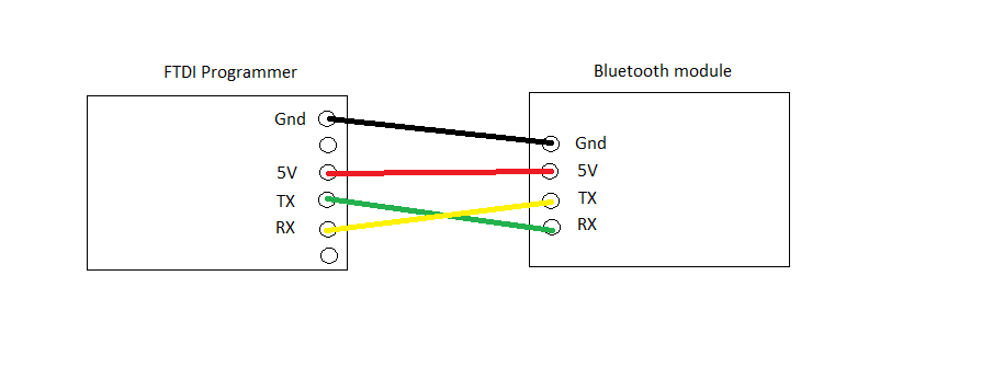
Soft serial setup
What remains is to select the GPS and receiver type you are using in the config TAB
Transmitter setup
Use the Receiver Tab in the Configurator and ensure that your transmitter
Send the channels within 1000 - 2000 range and centers 1500.
Failsafe will be triggered if the value falls below 995µs.
The failsafe threshold can be changed in cli.
Send the channels within 1000 - 2000 range and centers 1500.
Failsafe will be triggered if the value falls below 995µs.
The failsafe threshold can be changed in cli.
Soft serial setup
Failsafe setup
The preferable way to detect a Lost connection is to program the radio to
Stop sending PPM/PWM signals.
Or to program it to center all channel and trim throttle channel below the threshold value.
Stop sending PPM/PWM signals.
Or to program it to center all channel and trim throttle channel below the threshold value.
Servos
If the Gyro compensate in wrong direction when you move the plane.Change the direction in the servo TAB.
Endpoints should be set in the Gui and not in the Transmitter.
The parameters for the Navigation.
Max allowed influence from GPS code in degrees.fw_gps_maxcorr = 20 // Max Roll input from GPS (For Flying wings set to >=30)
fw_gps_maxclimb = 15 // Max Climb input
fw_gps_maxdive = 15 // Max Dive input
fw_gps_rudder = 15 // Max Rudder input if rudder is available
fw_climb_throttle = 1900 // Limits Throttle during climbs
fw_cruise_throttle = 1500 // Suitable average throttle
fw_idle_throttle = 1300 // Lowest throttle during Descending
fw_roll_comp = 100 // How much Elevator compensates Roll in GPS modes
fw_rth_alt = 50 // Min Altitude to keep during RTH. (Max 200m)
small_angle = 180 // Will allow the Plane to be Armed in any position.
GPS modes Need to be activated together with Angle or Horizon modes.
Flight Modes
Passthru = Manual flight Mode
All stabilization is disabled.
Acro = Normal mode
Gyro Stabilization is active..
Horizon = Stable mode
Gyro And Accelerometer To return the plane to level.
PosHold + ANGLE = Hold position mode
Uses Gps to Circle the point where it was activated.
RTH + ANGLE = Return to home mode
Uses Gps to return home.
Starts circling after return
RTH + ANGLE = Auto Launch mode
Use RTH to launch the plane.
Activate before launching.
Will Climb to RTH altitude and
Starts circling around home.
Starts circling after return
RTH + ANGLE = Auto Launch mode
Use RTH to launch the plane.
Activate before launching.
Will Climb to RTH altitude and
Starts circling around home.
Failsafe RTH = Emergency Return mode
Uses Gps to return home.
Will attempt to land the plane when returned.
Advanced setup of Custom servo mixer
Setup a CUSTOMPLANE
All servos can be programmed with different functions.Baseflight Gui now have a working servo mixing tab to use.
Before it was supported by Gui i created a simple
Windows App to setup Custom Airplane
Download ServoMixer_CLI.exe (right click save as!)
Servo = OutputServo
Input = Selected source
Rate = % rate and reverse with minus.
Speed = Higher is faster.(3 gives a nice speed for Flaps )
Min/Max = Endpoints 0 - 100 // 50 = Centerpoint
AUX select = Activate the rule with a AUX switch. zero for always active.
Create new rules
Select Output servo,Input,Rate, Min, Max and controllBox
Press Add to complete.
Add the mixers you need for your model.
Press modify to save the modification.
Organize the list and move rules up or down.
Clear the list or fix the number order with
Reorganize button
Export mixers when done.
You can Copy the text and paste it in Baseflight CLI intercace.
Or select correct Comport and Send it direct to the NAZE board.
Baudrate is set to 115200.
Make sure The Comport is closed and no other programs is
connected.
A CLI window will be shown to verify the communication.
Press Back to close the comport again.
Now you can connect Your Baseflight configurator to NAZE again.


